Building a killer Radio control pilot for RCparaglider.com harness and UZI-1 Wing setup.
Video here or full Instructions and photos below
Supplies needed:
-12” action figure
-body weights small lead weights 2 bags of 1/4oz weights
- 2 low profile metal gear high torque servos
- 8 small screws 3/8” (servo arm mounting)
- 4 small servo mounting screws 3/8" long.
- Double sided tape
Tools needed:
- Dremel or like tool with cutting wheel
- Thin bladed hobby hand or hack-saw
- Hot glue gun
- Exacto knife
- Permanent pen
-CA thin Glue
Before starting to build or buy anything, I suggest reading through all of this information to help you make a perfect pilot and flying system. You will find tips and hints to help make the process that much easier!
BUILDING TIP 1- A hot glue gun is chosen as the glue method for a two reasons: 1) the glue is rubber-like and seems to absorb more before releasing and absorbs crashes without breaking things, and 2) if you ever have to remove anything or replace a servo it can be easily cut and/or melted to let you replace parts as needed. We call it pilot magic.
BUILDING TIP2- At all points of final mounting make sure to keep putting your pilot back in the harness to make sure alignment and build size is perfect!
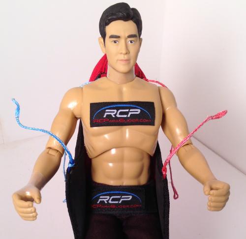
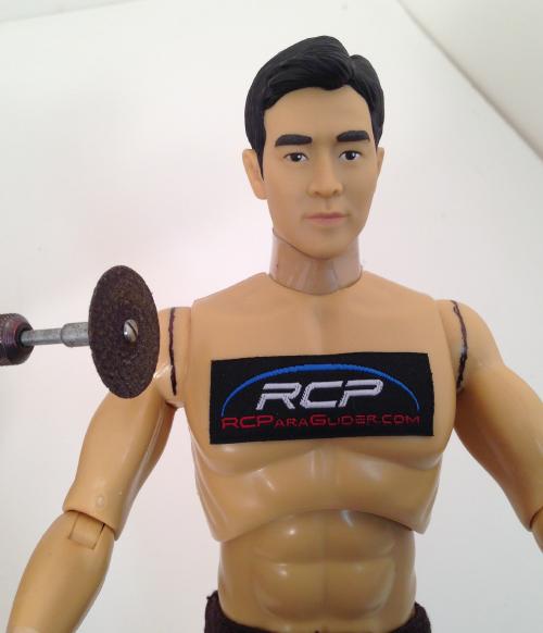
Step 1 - Choosing the right action figure/pilot: The wing and harness are designed to work with just about any 12” standard action figure, such as a GI-Joe or Star Trek character, etc. Of course the males are built wider and bigger and accept the larger servos better for a more realistic look than the females, but my future plans are to build some female pilots as well. There are many action figures out there that will work great. I have chosen the ones for sale on this website based on their build, ease of building into pilots, and realistic look. NOTE: the great thing about choosing a standard action figure is you can go onto Ebay and buy just about any actor or famous person’s molded head to fit your pilot, and the clothing selection is tremendous, which just makes it that much more fun!
Step 2 - Servo selection: The best servos are metal geared low profile high torque servos. Metal gears take the punishment of crashes and are stronger, enabling movement of the longer arms that are going to attach to them. Low profile servos, such as those sold on this website, also allow the servos, in most cases, to be mounted bottom to bottom, with nothing except possibly a small spacer to get the correct distance for the shoulder spacing. The servos for sale on this site work well and make it easy to follow these directions for a successful ready-to-rock pilot.
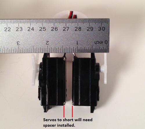
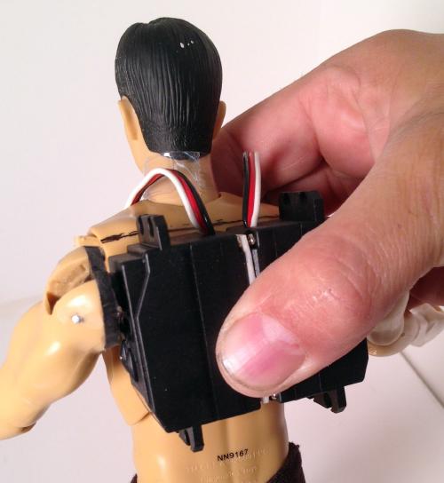
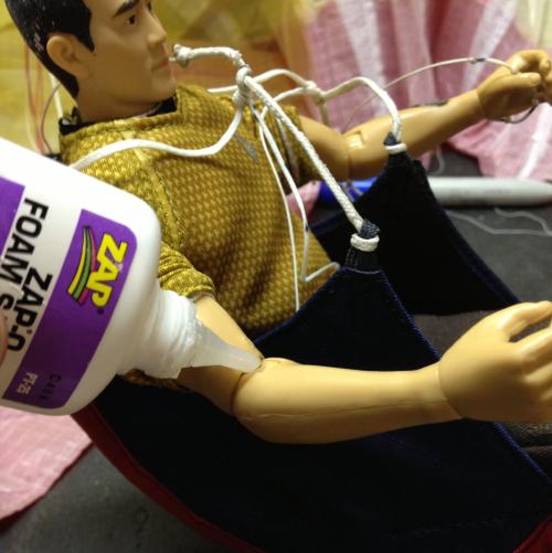
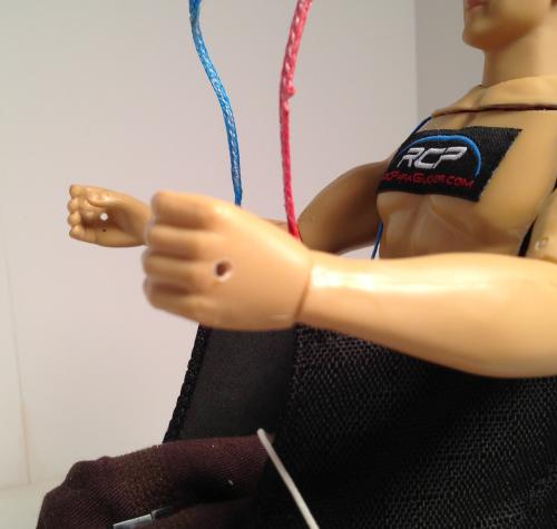
Step 3 - Measuring the distance for shoulder spacing and servo placement: Place your pilot into the harness [PIC-1]. A good rule of thumb is to make sure that your pilot’s hands keep a spacing of anywhere from 4” to 4 ½” [PIC-2]. This allows the pilot’s arms adequate clearance from the harness when the arms are in action/flying. Once the pilot’s arms are set, mark where you are going to cut them. Hold your servos, with servo arms attached, bottom to bottom to measure width and check spacing [PIC-3]. The ideal width is 2 1/2” to 2 ¾” outside to outside, as shown below. Some servos measure perfectly; others need a spacer to achieve the ideal width. Now that you have determined approximately where your servos will be inserted into your pilot (chest area), use the permanent marker to indicate a cut line around the shoulder area on each of the pilot’s arms. Ideally, cutting will be at the thickest part of the pilot’s arm/shoulder to allow more surface area for attaching the servo arms [PIC-4]. Once you have them marked, measure the distance between these lines. This measurement will help in Step 5 and should be in the range of 2 1/2” to 2 ¾”.
 1
1 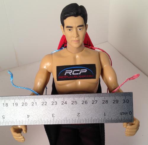 2
2 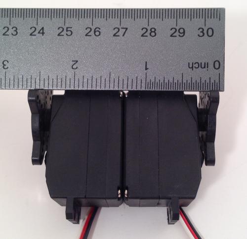 3
3 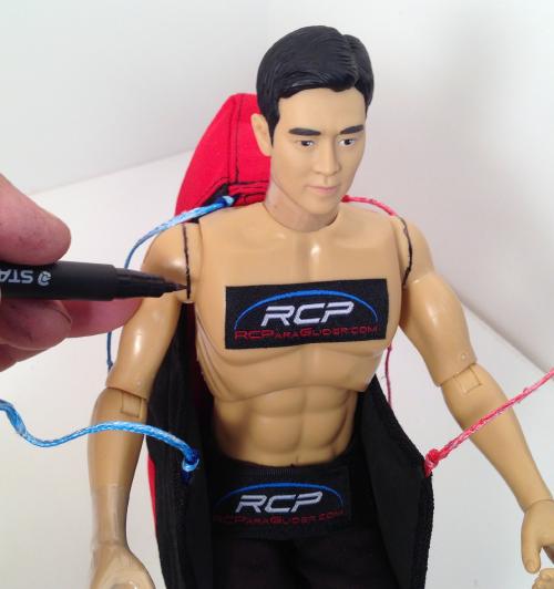 4
4
Step 4 - Cutting pilot’s arms and mounting servo arms: Using the Dremel tool, cut and remove the pilot’s arms by cutting around the marks you made in Step 3 above [PIC-1a, b].
HINT- Remember cutting too much can be a problem while cutting too little allows you another chance if you make a mistake.
After removing the pilot’s arms, use the Exacto knife to “clean them up” and produce a flat clean surface area ready for attachment of the servo arms. Determine placement of the servo arms for attachment to the pilot’s arms [PIC-2]. Attach each servo arm to the corresponding pilot’s arm using at least 4 screws. If your servos do not already have holes for at least 4 screws, you will need to make more holes in the servo arms [PIC-3]. After servo arms are mounted and screws are placed, use your Dremel tool to cut away any extra servo arms that extend beyond your pilot’s arms and/or shoulders. This will allow smooth movement of the arms inside clothing [PIC-4].
 1a
1a 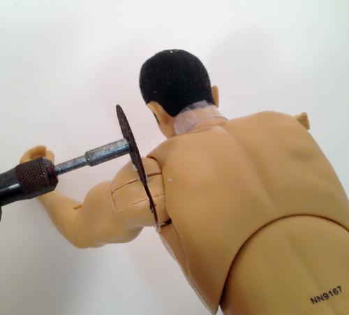 1b
1b 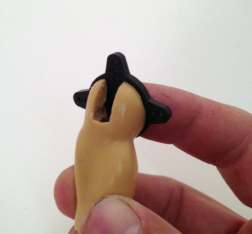 2
2 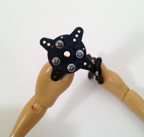 3
3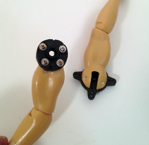 4
4
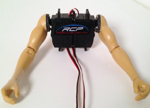
Step 5 - Connecting servos to create a control unit: If you are using the servos sold on this website they can simply be taped together using double-sided tape [Pic-1]. If your servos are smaller than what is shown in Step 3 Picture 3, then continue on with this step.
Attach each servo to the corresponding servo arm, then hold the servos together and measure the total “control unit” width to determine if you need to add a spacer or if your control unit width is the appropriate size (2 ½” to 2 ¾”). If you need to add a spacer [PIC-2] you can use many things for this, including wood (not balsa), plastic, rubber, or just about anything that’s close to the distance needed and stiff enough to make a solid mounting surface. Trace the bottom of the servo on this material and cut it out. Now glue or stick the servos and spacer together with strong double-sided tape or Glue.
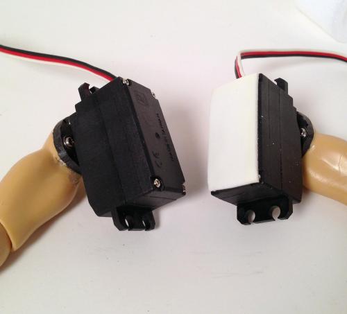
PIC-1 HD servos from Website, simply stick together PIC-2 other servos that will work but need spacer. Servos and arms ready to mount in pilot
Step 6 - Marking and cutting the body for servo placement: Hold up the completed control unit (with pilot’s arms attached) to your pilot’s body where it should be placed within the body area, making sure to line up where the shoulders should or used to be [PIC-1]. Using the permanent marker, indicate the control unit’s top edge (along the top of the back) and bottom edge (around the waist) [PIC-2]. These marks should be the where the main servo body ends on the control unit, not where the servo mounting flanges end! The flanges will be utilized later in the building process. Using the Dremel tool with cutting wheel, start cutting along these lines to dismantle the pilot. Some of the action figures have internal structure, and you may need a small hand saw to finish cutting what the Dremel wheel can’t reach. Now that you have all pieces cut, you are ready to fit the servo control unit for mounting [PIC-3].
 1
1 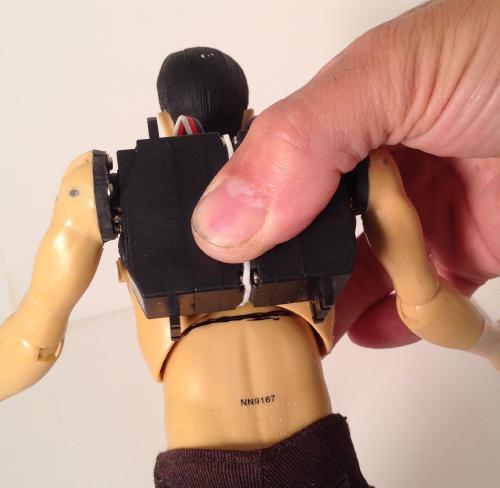 2
2 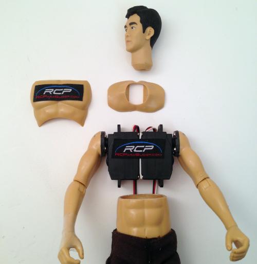 3
3
Step 7 - Final mounting location of servo control unit: NOTE: Do NOT glue or mount anything in this step!
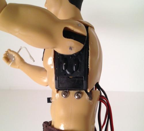
This step takes a little trial and trimming and fitting to get things just right. It’s not hard, just part of the hobby. This is where those servo mounting flanges come into play. The overall goal is to trim areas as needed using the Dremel or other cutting tool to get the flanges to mount up into the shoulder and/or down into the waist area. This will enable them to be used with either screws or glue to mount solidly onto these areas. Notice in the picture of the waist [PIC-1] I have made small trims to allow screws to be used to mount the servos at the sides of the lower body. At the shoulders I have made cut outs so that I can glue with the glue gun to mount them onto the tops of the servos [PIC-2]. I have also trimmed these flanges to fit nicely [PIC-3]. So again it can take a little trial and trimming to get things perfect.
 1
1 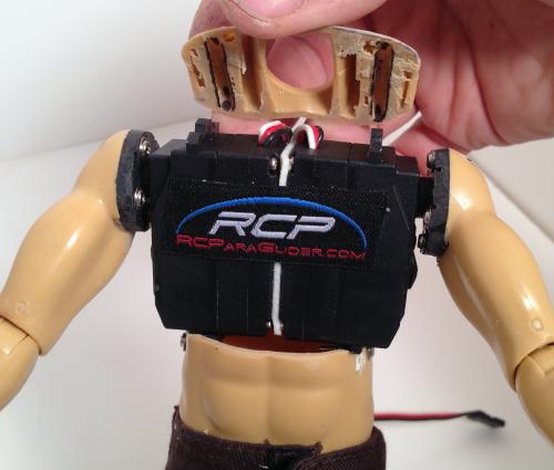 2
2 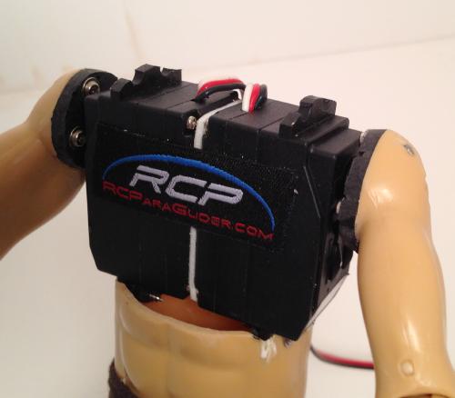 3
3
Step 8 - Switch mounting preparation and body pre-weights: Now that you have your servo control unit ready to be mounted and its location determined, it’s time to prepare to mount your switch and put your pre-weights into the body cavity. NOTE: Nothing will actually be attached in this step.
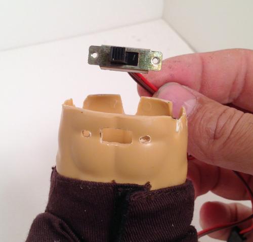
Switch mounting- Mounting the switch in the belly button area is a nice touch and makes it easy to access and hide under the clothing. Mark an area where the switch can be mounted. Using your Dremel with a small cutting bit makes this step easy. Cut a big enough area so the switch toggle can poke through and move freely. [PIC 1] and [PIC-2]. Once this area is cut out, drill a small hole on each side for your 2 mounting screws to attach the switch to the body. DO NOT attach switch mounting yet.
Body pre-weights- This is where those small 1/4oz weights come in. I have found that all my pilots need pre-weighting inside of them if at all possible. This prevents always having to add ballast in the harness for light wind flying [PIC-3]. Once your switch location has been figured out and installed, you can put small weights down into the lower open body cavity to determine how many will fit in the area.
 1
1 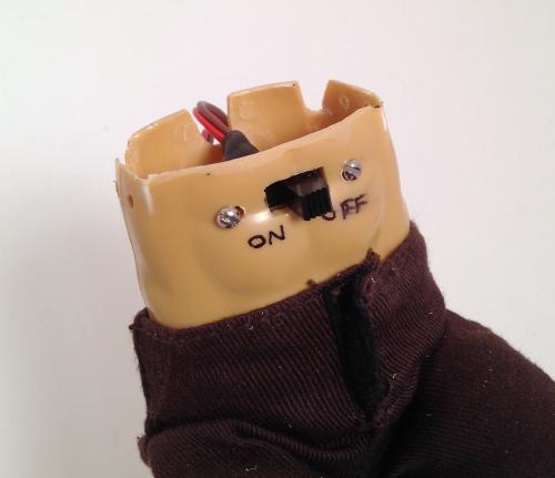 2
2  3
3
Step 9 – Assembly: Now that you have determined how many small lead weights will fit into the body cavity and still allow the switch and lower servos to be mounted, you are ready to assemble. Start hot gluing the weights into the body cavity. Mount your switch and then put a few more weights around the area, gluing as you go [PIC-1]. Now with all the weights glued into place and the switch mounted, you are ready to install the servos onto the lower half of the body. Once everything is aligned to accommodate the servo control unit, use hot glue around the edges and/or inside to attach the servos, then use the small screws to complete the attachment and secure everything into place [PIC-2].
 1
1 .jpg) 2
2
Step 10 - Mounting shoulders, chest, and back: Now it’s time to add the finishing touches to make your pilot look realistic. Start by gluing and mounting the shoulders. Again, hot glue works perfectly. Then cut off the chest and back areas that were removed from the action figure in Step 6 and glue them onto the servo control unit [PIC 1]. If cutting the plastic parts seems too difficult, simply cut pieces of styrofoam and glue them onto the back and front areas and sand to shape as desired.
PIC-1
Step 11 -
Final touches:
Head attachment: Put your pilot back into the harness and determine desired head placement and angle. Attach head with hot glue or CA. NOTE: Remember that Ebay has a great selection of 12” action figures. You will be amazed at what you can find there!
Glue arm joints: Position the pilot’s hands so they are 4” to 4 ½” apart and the arms so they look realistic and are clear of the harness. Use thin CA glue to glue all the joints in the elbows and wrists into place so they will remain stationary [PIC 1].
PIC-1
Mounting brake lines: The next task is to determine how you want to mount your brake lines in the pilot’s hands. I have found drilling a small hole in the hands and pulling through a loop to loop line is very easy and efficient [PIC 2]. All connection points onto the wing use a larks-head knot to connect. I like how simple and clean it is (versus heavy, clunky metal clips). It also enables settings to be changed and the wing to be removed very easily. These line extensions have a small loop at the hand and extend up to about 1 ¾” from the hand [PIC-3].
 2
2 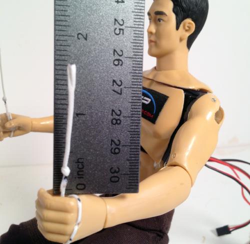 3
3
Your Pilot is now ready to setup in the harness, install battery, reciever and setup arm placement.. Here area a few photos showing where your battery and reciever are placed in the back of the harness.
On some of my pilots I have installed the small Micro Orange recievers directly on the back of the pilot with no problem at all, but when a larger reciever was used I have found they fit well in the back of the harness with the battery.
The hareness comes with a full foam insert in the back of the harness, this foam can be cut at any location to install battery and or receiver. The lower large section of the harness is designed to take plenty of Lead Ballast weights
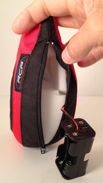
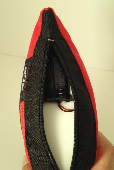
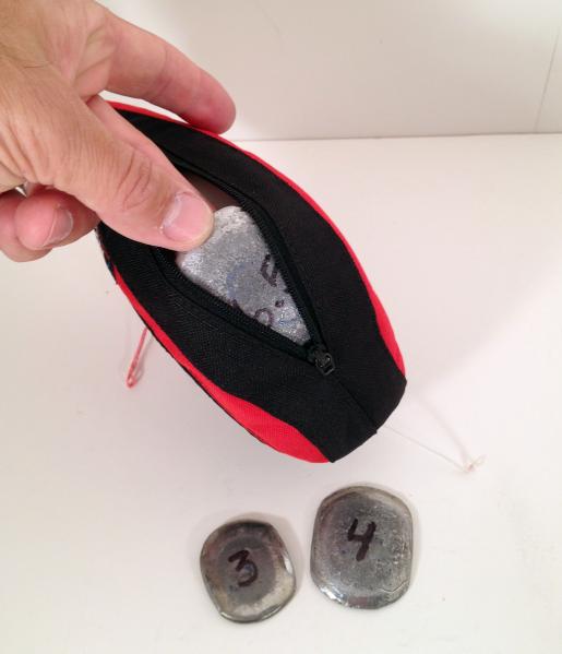
Cut out for battery placement Battery installed into upper section Installing ballast in lower section.
Thank you everyone for reading. Believe me I'm not a writer by any means so. If you have any tips or hints that I can change in these instructions to help other please feel free to let me know!
Jeff Howard
info@rcparagliders.com